Wukong Architecture
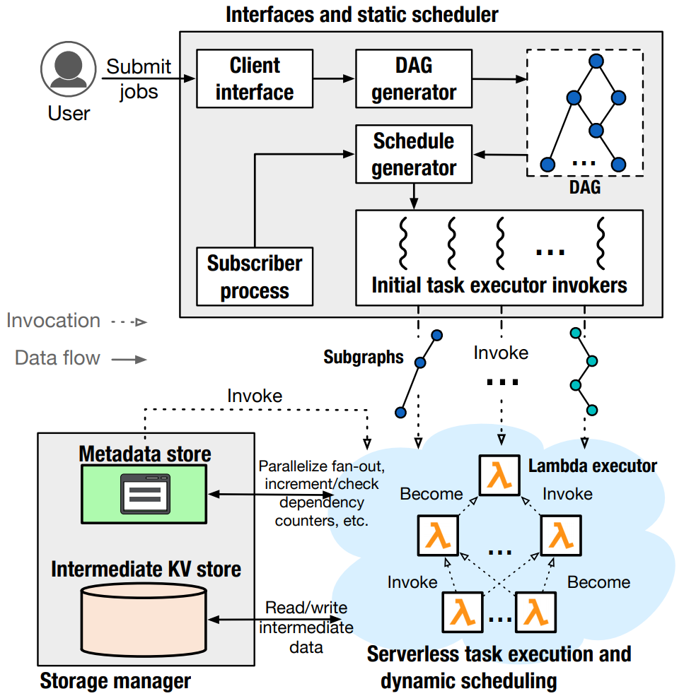
Wuking is composed of three primary components: 1. Static Scheduler 2. Serverless Task Executors 3. Storage Manager
The following sections will describe these components in greater detail.
Static Scheduler
The Static Scheduler in Wukong serves as a front-end client interface to the framework. Users can submit jobs via the Client Interface. These jobs will be passed to the DAG Generator, which will convert the user-written Python code into an executable DAG.
The generated DAG will then be handed off to Wukong’s Schedule Generator. The schedule generator performs a series of depth-first searches on the DAG to partition it into a collection of sub-graphs, referred to as static schedules. Finally, the static schedules corresponding to so-called “leaf tasks” (i.e., tasks with no data dependencies) are assigned to Serverless Executors by the Initial Task Executor Invokers. Specifically, the static schedules are serialized and included in invocation payloads for the Serverless Executors.
Serverless Task Executors
The Serverless Task Executors (often referred to simply as “Executors”) are the workers of Wukong. Each Executor is simply an on-going invocation of the AWS Lambda function. When an Executor begins running, it retrieves its assigned static schedule from the invocation payload or from intermediate storage. (Invocation payloads have a size limit of 256kB, meaning some data may need to be stored in intermediate storage rather than included directly within the invocation payload.) When an Executor runs out of work, it simply terminates, rather than waiting for more work from the Scheduler or fetching more work from an external queue.
Dependency Tracking
Executors communicate with one another through intermediate storage. Each task in the DAG has an associated “dependency counter” maintained within the Metadata Store (MDS), a component of the Storage Manager. Each time an Executor completes a task, the Executor increments the dependency counter of each of the completed task’s dependents. Executors can check whether a task is ready to execute by examining the value of the task’s dependency counter. If the value of the counter is equal to the number of dependencies of the task, then the task is ready to execute. To better illustrate this process, consider the following example.
Dependency Tracking Example
The diagram below shows a simple DAG containing three tasks: Task A, Task B, and Task C. This DAG will be executed by two Executors: Executor #1 and Executor #2.
Looking at the structure of the DAG, we can see that Task C is dependent on Task A and Task B. As a result, Task C will not be able to execute until both Task A and Task B have been completed.
Assume that Executor #1 completes Task A first (i.e., before Executor #2 completes Task B). Executor #1 will next examine the dependents – also known as the downstream tasks – of Task A. In this case, there is just one downstream task, Task C. Executor #1 will increment the dependency counter of Task C by 1, thereby indicating that one dependency of Task C has resolved (i.e., has been executed).
After incrementing Task C’s dependency counter, Executor #1 will check to see if Task C is ready to execute. It will compare the current value of Task C’s dependency counter against the number of data dependencies of Task C. In this case, Task C has 2 dependencies and its dependency counter has the value 1. Because these values are not equal, Executor #1 will determine that Task C cannot be executed yet, and Executor #1 will terminate. The result of this is shown in the diagram below.
Next, assume that Executor #2 completes Task B. Executor #2 will next check for any downstream tasks of Task B and discover Task C. Now Executor #2 will increment the dependency counter of Task C. Prior to this increment operation, the value of Task C’s dependency counter is 1. After Executor #2 increments Task C’s dependency counter, the value of the counter is 2. Executor #2 compares the value of Task C’s dependency counter against the number of dependencies of Task C.
At this point, Executor #2 will find that the two values are equal (they are both 2). Executor #2 will conclude that Task C is ready to execute. In order to execute Task C, Executor #2 will first retrieve the output of Task A from intermediate storage. Once obtained, Executor #2 will have satisfied all data dependencies of Task C and will proceed to execute Task C.
Nam erat dolor, porta sit amet ultricies vel, scelerisque at sapien. Quisque eleifend magna at pharetra suscipit. Proin eu pretium nisi. Praesent ante velit, hendrerit vitae sagittis sit amet, ultricies ac dolor. Vivamus pharetra vitae nisl et ornare. Pellentesque tincidunt eleifend accumsan. Sed augue nisl, sagittis ut scelerisque eu, imperdiet quis nisi. Praesent auctor consectetur risus, in lacinia elit consequat ac.
Storage Manager
The Storage Manager abstractly defines the intermediate storage of Wukong. It is composed of a Metadata Store (MDS) and an Intermediate KV Store (KVS). The MDS is simply a single instance of Redis running on an AWS EC2 virtual machine. The KVS is an AWS Fargate cluster in which each AWS Fargate node is running a Redis server.
The Metadata Store (MDS)
The MDS is simply a Redis server running on an AWS EC2 virtual machine. Typically, the MDS will be running on a separate EC2 VM from the Static Scheduler. There is also a KVS Proxy running on the MDS virtual machine. The KVS Proxy aids in invoking downstream tasks and storing and transferring intermediate data. Typically, the KVS Proxy is only utilized in cases where many downstream tasks need to be invoked all at once. The higher network bandwidth of the KVS Proxy is beneficial in transferring intermediate data to newly-invoked Executors.
The Static Scheduler stores static schedules and dependency counters in the MDS at the very beginning of a workload. Executors will fetch static schedules and increment/retrieve dependency counters during a workload’s execution. Additionally, the final result(s) of a workload will be stored within the MDS rather than the KVS.
The Intermediate Key-Value Store (KVS)
The KVS consists of an AWS Fargate cluster. The Wukong static scheduler will scale-up the AWS Fargate cluster according to the user’s specification. Each virtual machine within the AWS Fargate cluster will be configured with 4 CPU cores and 32GB of RAM (though users could modify these values if they desire). Each of the AWS Fargate nodes houses an active Redis server. Intermediate data is stored in these servers during a workload’s execution. Data is consistently hashed across the entire AWS Fargate cluster in order to ensure a relatively balanced distribution of data.